






Designing timber beam connections for the actual structure
Roof coverings
A timber beam connection must suit the forces and position in which it works, not merely hold two pieces together. Conditions beside a support differ from those at midspan, and rotation, slip and uplift also matter. Notches, steel connectors and nail or screw patterns should therefore follow the design documentation. This guide explains what to check when selecting a detail, preparing timber and inspecting work before concealment. It offers no universal joint to copy across every roof or canopy. Adding fasteners or cutting a deeper recess can worsen performance. Establish loads and support requirements first, then select compatible components and a safe erection sequence.
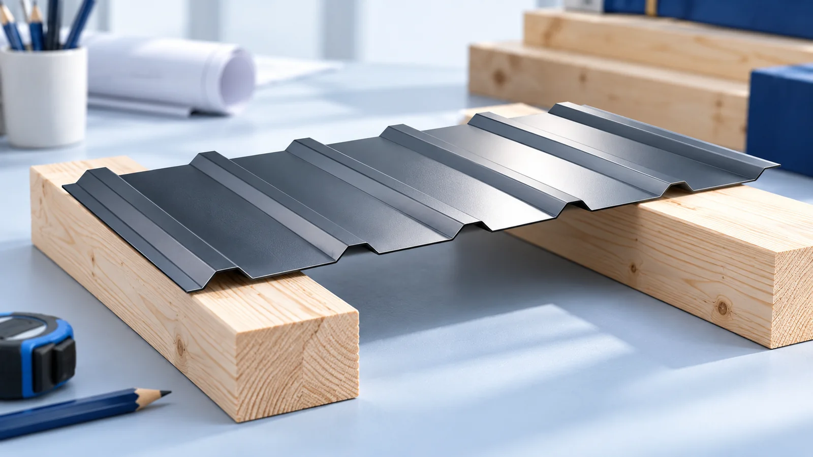
Why does connection position matter more than appearance?
Forces vary along a beam, so a detail intended beside a support may be unsuitable at midspan. Relocating a joint requires reassessment. Similar timber geometry does not imply similar loading at the chosen position.
A connection may transfer compression, tension, shear or bending and restrain slip or rotation. A snug fit alone is insufficient. Establish which forces and movements the detail is intended to resist.
When are traditional carpentry joints appropriate?
Notched and lap joints rely on contact between properly prepared surfaces. They require accuracy and sufficient remaining cross-section. Deepening a recess simply to ease assembly can weaken the beam.
A bearing joint may need additional fasteners against separation or uplift. Contact between timber surfaces can disappear when the loading direction changes. Member weight does not prove that the detail resists every required action.
What do steel connectors provide?
Use angles and hangers according to documentation specifying substrates, fasteners and loading. Similar-looking products may differ in thickness, hole pattern and purpose. Selection by appearance alone does not establish an equivalent connection.
Use the nails or screws specified for the connector. An arbitrary countersunk or plasterboard screw cannot replace a structural fastener merely because it fits the hole. Check the complete assembly, not just the steel fitting.
Which fastener-layout mistakes should be avoided?
Distances from timber ends and edges affect splitting risk. Closer screw spacing does not necessarily increase capacity. Do not drill extra holes in a steel connector without confirmation that the modification is permitted.
Some systems allow documented partial fastening patterns for stated capacities; not every visible hole must always be filled. Choosing every other hole independently is not equivalent. Fastener position matters as well as quantity.
How should timber and the work sequence be prepared?
Check dimensions, moisture, contact surfaces and bearings before assembly. Do not force distorted members into place with a bolt without identifying the cause. Compare deviations with permitted tolerances and agree a correction method.
The erection sequence should define temporary supports and bracing. During renovation, do not drill or cut a loaded member without a plan to relieve it. The finished joint and the construction stage require separate safety considerations.
Assess cracks by their position, extent and effect on the connection. Not every check condemns a beam, but cracking near fasteners cannot be ignored. Adding an arbitrary plate is not evidence of an effective repair.
What should be specified and inspected?
Provide the contractor with the joint location drawing, timber dimensions and complete fastener specification. Match corrosion protection to exposure: a dry interior and an open canopy differ. The word galvanised alone does not establish suitability for every application.
Before concealment, compare installation with the documents, record product identification and take photographs. Any substitution needs confirmed compatibility with the design. The objective is predictable load transfer, not the greatest possible number of screws in the timber.

Free quote
What to include in your enquiry
Tell us how you plan to use the material, the dimensions and the quantity you need. Include the thickness, grade or variant name, along with the delivery town or your preferred collection branch. For a specific product, add its name or a link to the product page. We will reply to the email address you provide to discuss availability and the terms of your order.



More from the building guide
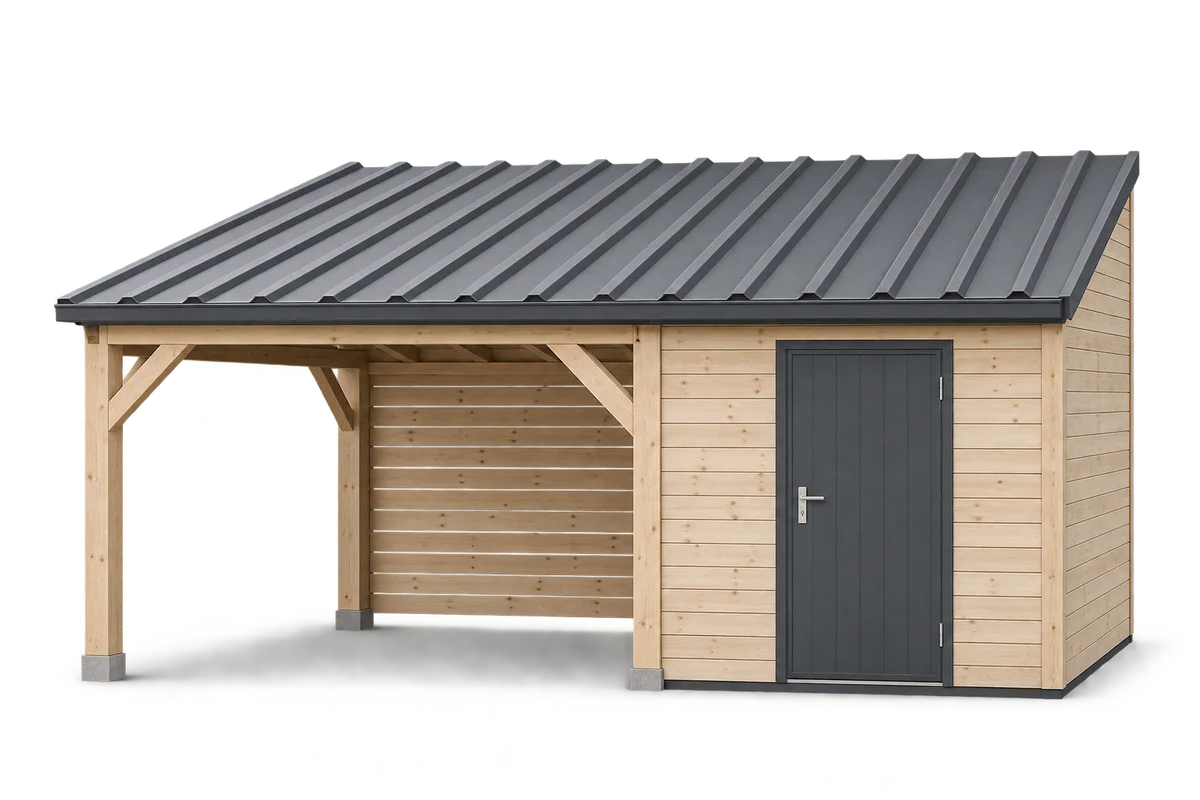
Start planning a carport with a tool store by listing the equipment and the routes people use every day. A mower, bicycles,…

Assess metal pickets on a trial fence panel showing the gaps, both coated faces and access to fixings. Their benefits include manageable…

Assess a metal picket fence as a complete arrangement of posts, rails and infill. The pickets determine colour, rhythm and screening, but…
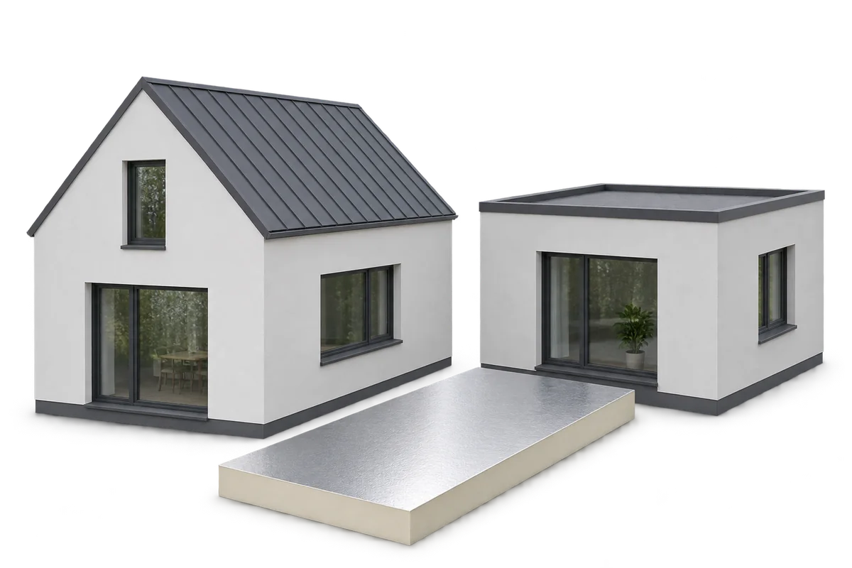
Passive house design starts with the site and the layout of the rooms. These decisions guide the choice of insulation, windows and…
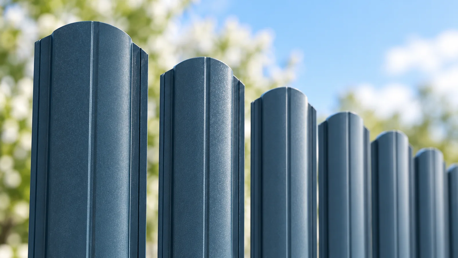
Choose a metal picket fence panel as a combination of infill, rails, posts and fixings. Colour alone does not determine privacy or…

The catalogue price of a house plan covers only part of the cost of the documents you need to build. Check whether…

Under Polish building law, a detached single-family house with a footprint of up to 70 m² and no more than two storeys…