






Designing a steel production building around the process
Steel buildings and structures
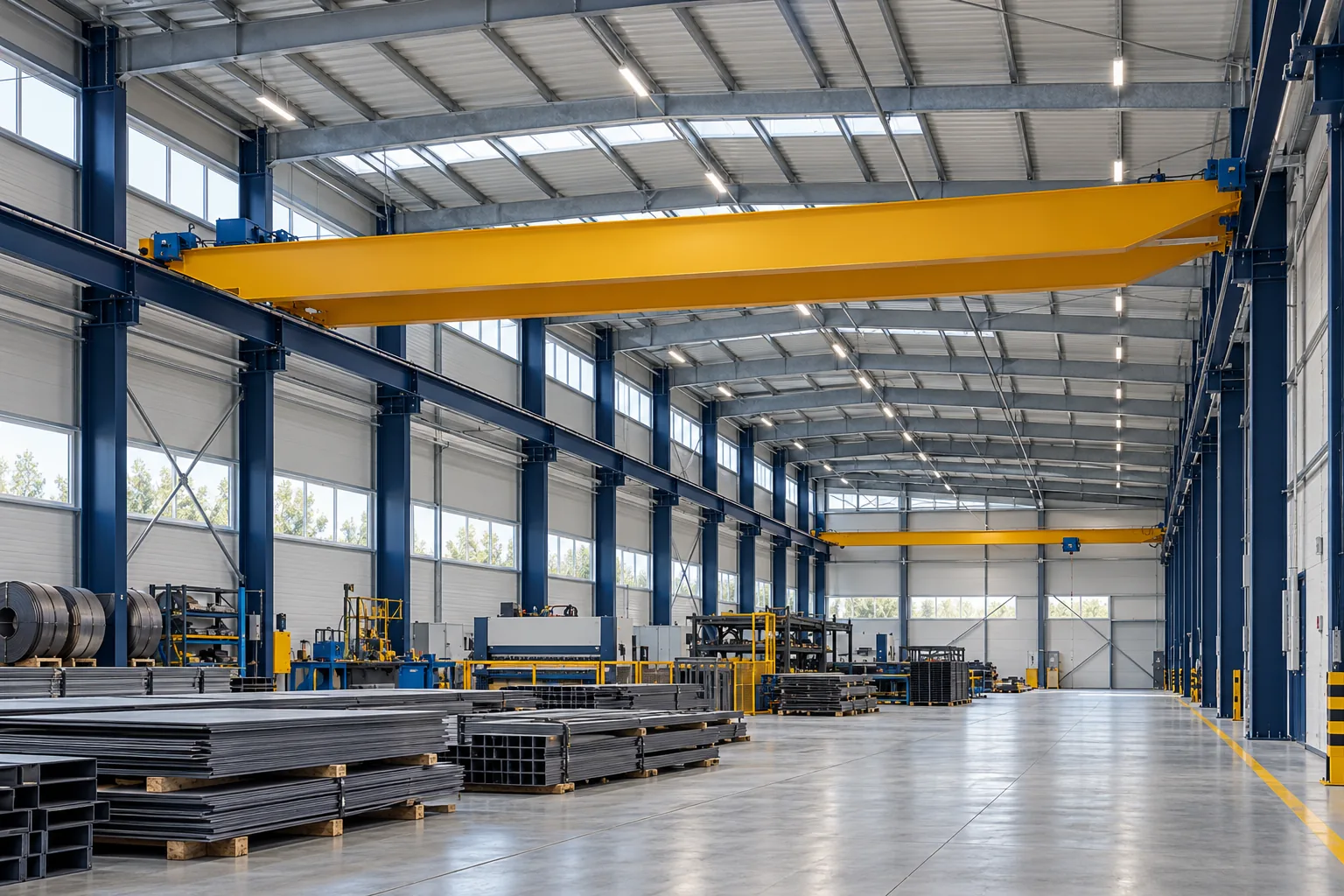
Start a production building design by tracing the process from goods receipt through machining, inspection and dispatch. Mark where unfinished work waits, where waste is collected and where operators need to cross a material route. The machine footprint is only one of the dimensions that matter. Installation, tool changes and component removal all need space. The steel frame and foundations must carry the specified equipment loads, including moving loads where relevant. Use a shared layout for the process engineer, structural designer and services team before fixing the building height, column positions and door openings.
Trace material movement through the plant
Draw open guards and doors, the space to change tools and the path for withdrawing the largest serviceable component. Plan how each machine enters the building. Include the actual columns and bracing on the delivery route and check how pedestrian access will work during a busy shift.
Give the engineer the equipment loads
For each machine provide its weight, support points and installation requirements. Equipment that vibrates also needs dynamic operating data. A machine may require a separate foundation or vibration isolation. Check the floor design against these requirements before installation.
Show the weight and load transfer points for suspended ducts, pipes and rooftop plant. Include planned solar panels. If future services need a structural allowance, specify the loads and locations so the engineer can verify the available capacity.
Select the crane before setting the building height
Coordinate crane selection with building design. Specify lifting capacity, span, lifting height and duty. The bridge, hoist and load itself all occupy space. Check the required hook height together with headroom above the crane and clearance along its travel path.
A top-running bridge crane transmits loads through its rails and runway beams to the supports. Horizontal and dynamic forces also act on the frame and foundations. Retrofitting a crane requires an assessment of the existing building even where there is enough physical clearance under the roof.
Coordinate services with frames and roofing
Plot electrical supplies, ventilation and process utilities with their service access. A large duct beneath a girder can restrict an internal transport route. Position roof penetrations in relation to the purlins and the cladding joints.
Any opening in a load-bearing member needs an approved structural detail, including small service penetrations. Review frame, services and fire protection on the same drawings. Mark each attachment and specify how penetrations will be sealed.

Match the working environment to the process
Identify sources of heat, moisture, dust, noise and fumes. Where pollutants arise at a particular machine, assess extraction at the source alongside general ventilation. Size the air supply and extraction for the process and show how replacement air will reach the work area.
Arrange windows, rooflights and task lighting around workstations, considering overheating as well as daylight. Insulated sandwich panels can limit heat loss through a heated building’s envelope. Building services, door use and process energy also contribute to overall consumption.
Plan the relationships between departments
Workshop, storage and office areas can have different requirements. Coordinate their positions, escape routes and necessary separations. The process, materials and complete construction determine the fire protection measures and the fire resistance that needs to be demonstrated.
In the quotation identify responsibility for the building, services and production equipment, including their interfaces. Allow for equipment testing separately from building handover. For an overhead crane in Poland, include the applicable authorisation procedure before it enters service.
Define the next expansion step
A modular frame can support phased investment. Define what the next phase means for this building: a second line, another loading door or an extension at the gable. Each requires a different allowance in the original design.
Match the initial size to the production layout, document its loads and agree how capacity could increase. This gives the team a usable building now and a basis for assessing later changes.
Record each allowance in the drawings and calculations. Years later, the owner can then distinguish space reserved for equipment from structural capacity reserved in the roof or foundations for its weight.

Free quote
What to include in your enquiry
Tell us how you plan to use the material, the dimensions and the quantity you need. Include the thickness, grade or variant name, along with the delivery town or your preferred collection branch. For a specific product, add its name or a link to the product page. We will reply to the email address you provide to discuss availability and the terms of your order.
More from the building guide
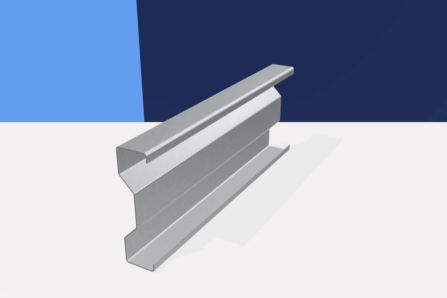
Cold-formed steel sections can form part of a canopy, garage or small industrial building. The design still has to account for wind,…
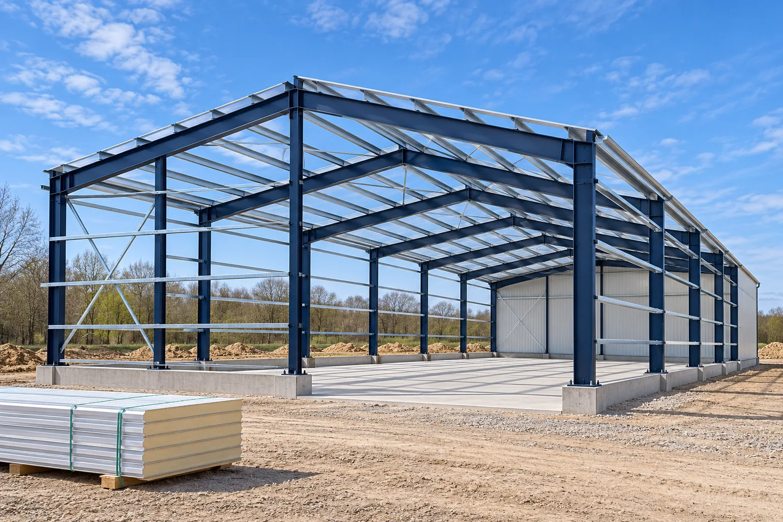
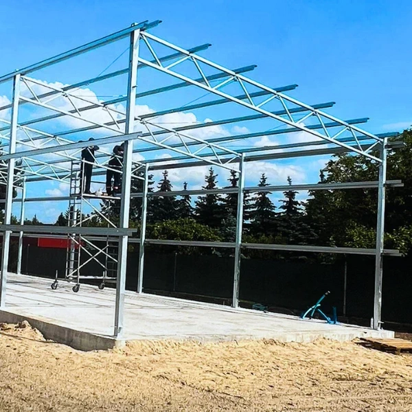
A steel frame can go up quickly once the site, foundations and deliveries are ready. Before ordering a hall in Poland, check…
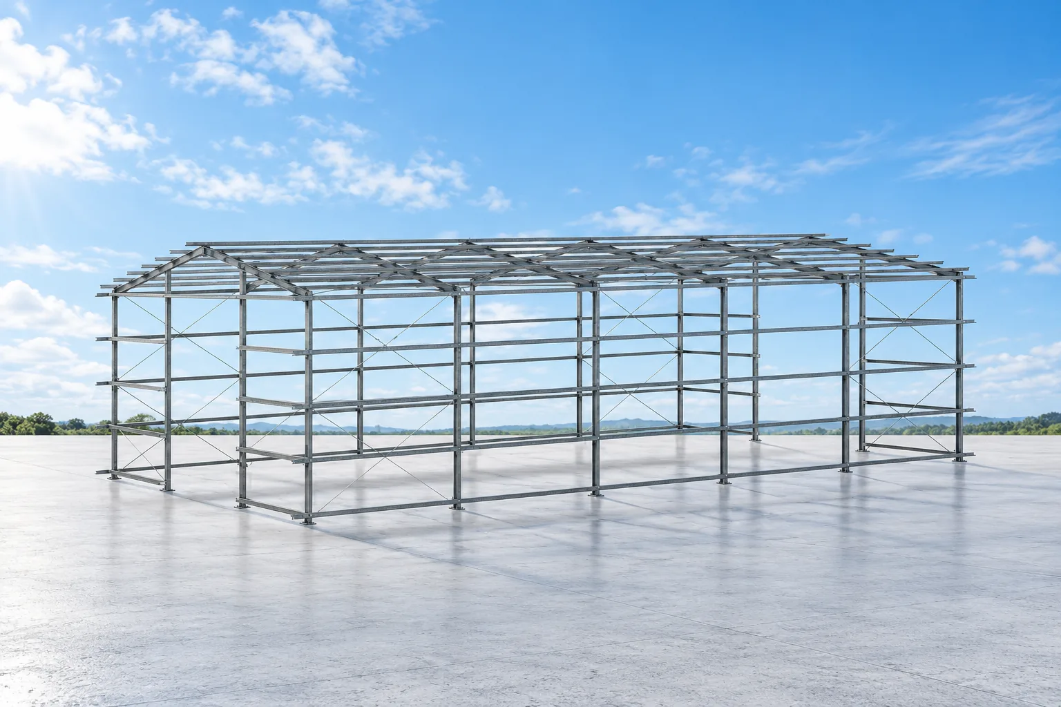
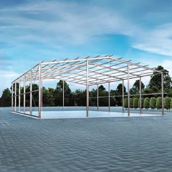
A standard steel frame kit gives you a defined starting point: a building width, a bay length and a roof shape. A…
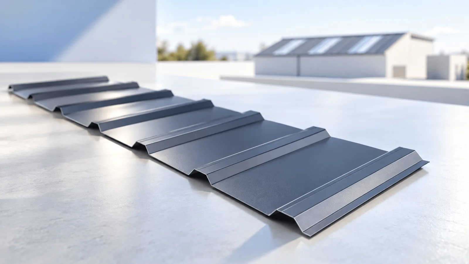
Choose a rooflight for the place you want to illuminate. Mark workbenches, shelving and overhead services on the plan: one large opening…
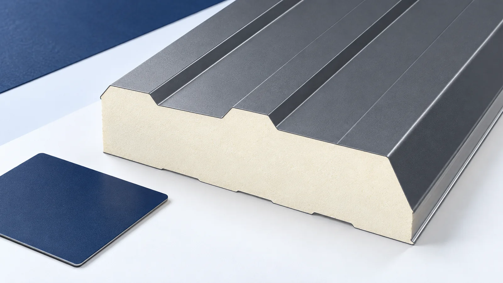
Design a hall roof around internal conditions and support layout, not the cheapest square metre of covering. An unheated shelter, warm workshop…
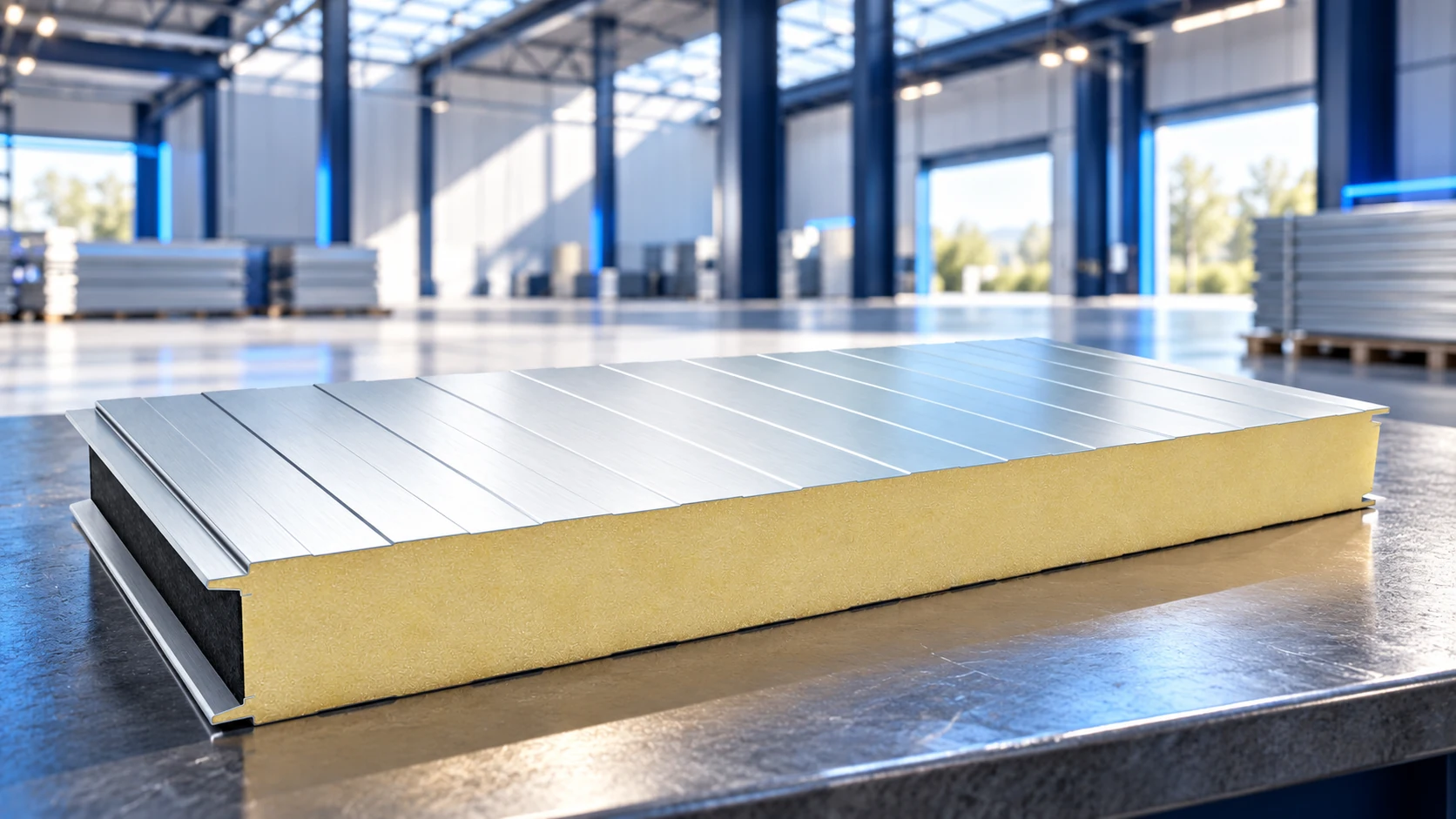
The cost of a sandwich-panel hall depends on the scope of the project. A frame with cladding is a different purchase from…
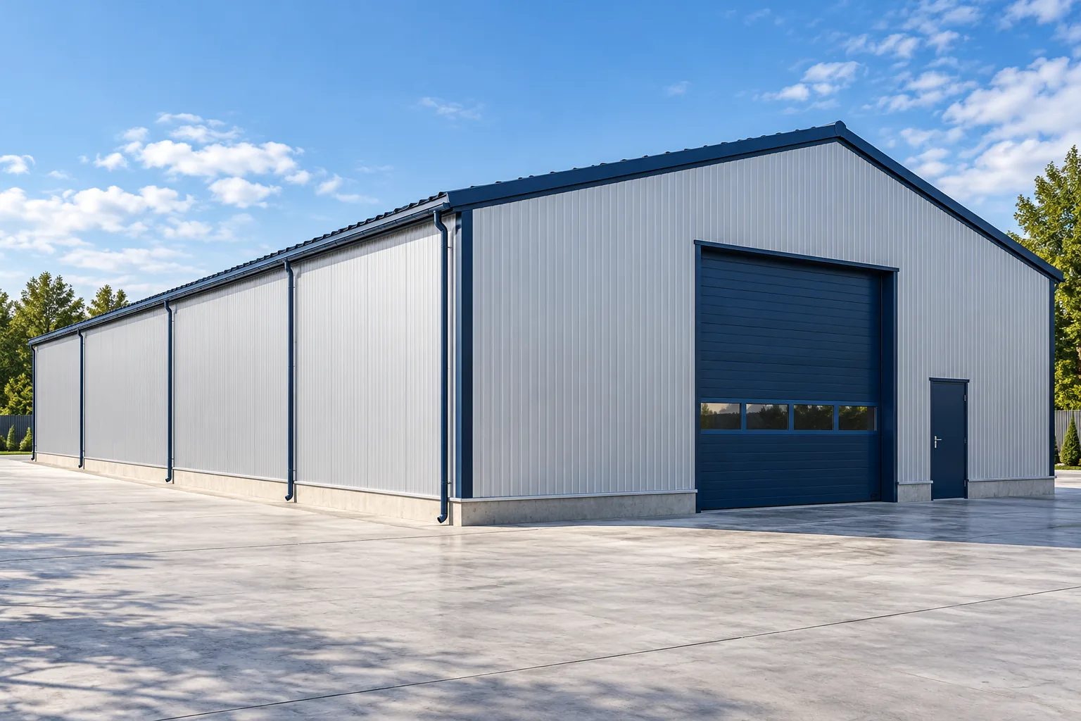
To choose between a standard steel building and a bespoke frame, draw the daily operation inside the proposed footprint. Mark delivery routes,…
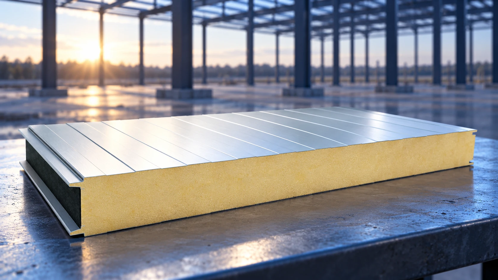
A steel hall's foundation connections must transfer the forces established by the structural design. Bonded anchors can form part of that solution,…